Skip to content
–
Pioneering state-of-the-art grazing spectrometers for basic physics research since 1987
  • Home
  • Hardware Products
  • Consulting Services
  • Applications
  • Staff
  • CONTACT US

hardware

HARDWARE PRODUCTS

services

Consulting Services

Hettrick Scientific Homepage

Hettrick Scientific Homepage

ES-SXR

Hettrick Scientific Homepage

StaffBanner

Staff

curriculum vitae

Curriculum vitae

publications banner

Publications

Quality Control

Publications

Applications

Applications

details VSA-200

Applications

details ES-XUV

details: ES-XUV

CAL-32

CAL-32 Custom Anode Library

details SNR-SXR

details: SNR-SXR

details TEFLAT/BLACKFLAT

details: TEFLAT-BLACKFLAT

Asides

TEFLAT/BLACKFLAT left detail

Download product pdf

TEFLAT™/BLACKFLAT™ gaskets provide many advantages when compared to conventional sealing materials for knife-edge flanges:

• Require much less force than copper, significantly reducing assembly time (and saving knuckles!).
• May be used with aluminum (or stainless steel) flanges and ports.
• Unlike copper gaskets, Teflon® gaskets are reusable, if not removed from flange and kept clean (number of re-uses may vary).
• Unlike copper gaskets, Teflon® gaskets do not tarnish with exposure to air.
• Unlike copper gaskets or o-rings, Teflon® does not react with most chemicals.
• Avoids the use of grease often necessary to keep thin section o-rings registered in place during assembly, particularly for a vertical flange orientation.
• Minimizes contamination of vacuum systems, particularly important for coating applications, high purity analyses and ultra-high vacuum applications.
• Unlike thin section o-rings, rigid Teflon® gaskets self-locate against the flange lip to provide a clear confirmation of a correct seal, preventing leaks and extruded o-rings.
• Less expensive than rectangular section o-rings.

TEFLAT/BLACKFLAT detail main

SIZES AND PRICING

Flange
outer diam.
Gasket
outer diam.
Knife-edge
diameter
Gasket
inner diam.
TEFLAT™
(white)
BLACKFLAT™
(black)
100 count 100 count
1.33″ 0.820/0.835″ 0.75″ 0.62″ $285 no stock
2.75″ 1.875/1.890″ 1.62″ 1.50″ no stock no stock
4.50″ 3.230/3.245″ 3.04″ 2.75″ $595 no stock
6.00″ 4.730/4.745″ 4.54″ 4.00″ $805 $970
8.00″ 6.730/6.745″ 6.54″ 6.00″ $1090 no stock
10.00″ 8.730/8.745″ 8.54″ 8.00″ no stock no stock

Note: Optional black color (model BLACKFLAT™) has carbon added to provide an opaque gasket for applications in which a completely light-tight seal is required, as some light which enters through the leak-check slots in knife-edge flanges will transmissively scatter through the white gasket.

TEFLAT™ and BLACKFLAT™ are trademarks of Hettrick Scientific.

Teflon® is a registered trademark of DuPont.

SNR-SXR left details

Download product pdf

U.S. Patent 5,274,435

  • Self-Focusing Concave Grating
    – High Throughput
  • Grazing Incidence: Soft X-Ray Use
  • Stationary Slits
  • Fixed Beam Directions
  • Fixed Numerical Aperture
  • Broadband Tunability

Specifications

Mounting
Hettrick, U.S. Patent 5,274,435; Spherical Grating
Angular Deviation
4.5°(Fixed). Nominal graze angle of 2.25°
Grating Stage Format
Gold Surface;
Active Circular Aperture 100 mm
Grating Groove Density
750 g/mm
Wavelength Range
10~100 Angstroms (m=1); approx. 6~50 Angstroms (m=2), depending on source intensity
Fractional Dispersive Resolution
0.167/mm (at Source and Exit Slit)
Optical Aberration (image tilt)
Δλ/λ < 0.010 at 6 mrad Sagittal Aperture, 10~50 Angstroms (m=1)
Meridonial Aperture
12.5 mrad, on Rowland Circle
Sagittal Aperture
0~30 mrad, astigmatic (Φ)
Exit Slit Width (Vacuum Selectable)
200 µm at 0.2°
100 µm at 0.2° (10-13 Å)
100 µm at 0.7° (13-20 Å)
100 µm at 1.2° (20-28 Å)
100 µm at 1.7° (28-37 Å)
100 µm at 2.2° (> 37 Å)
Exit Slit Length
20 mm
External Drive
Single Micro-Stepped Motor with Compumotor ZETA6104-57-83 Indexer/Drive w/RS232C Interface Port
Vacuum Chamber
Weld-Free 6061 Aluminum, Electroless Nickel Plated; TEFLAT/BLACKFLAT Sealed Knife-edge Ports
Entrance and Exit Ports
4.5″ Conflat Flange (ICF114)
User Ports
Three Ports Accept 2.75″ Conflat Flange (ICF070)
Length
0.63 meters (Slit-Slit)
Aperture Center
Stationary

Construction

Model SNR-SXR-0.6 is a high aperture (Φ = 12.5 mrad), single-element soft x-ray Monochromator. The grating has a 100 mm circular aperture with grooves extending to the edge. The distance from (slitless) source to exit slit is 628 mm. The fixed angular deviation of 4.5 degrees and gold coated grating provide efficient reflection to wavelengths as short as λmin = 10 Angstroms in first order and to approximately 6 Angstroms in second order. The spectral resolution is determined by the sagittal aperture which may be set by knife-edges at the entrance port of exit slit, over the range of approximately 0 to 30 mrad. A typical setting of 3 mrad (illuminating 2 mm at the exit slit) provides a fractional spectral resolution of 1/160 at 23 Å, 1/68 at 50 Å, and 1/33 at 100 Å. However, the long wavelength performance is improved considerably by employing an exit slit mask containing 6 slits (100 µm wide) at different angles, to match the image tilt over different regions in scanned wavelength. Using the appropriate slit, the resolution is approximately 1/100 over 10~50 Å using a 6 mrad sagittal aperture.

An externally mounted micro-stepping motor with Compumotor indexer provides rotational control of the grating scan under vacuum by means of a shaft feedthrough. The slits are also selectable under vacuum using a micrometer shaft feedthrough. Both the grating chamber and the slit chambers are electroless-nickel plated aluminum and are machined square relative to the grating surface and slit mask, enabling alignment by mechanical indication from the chamber exteriors.

The photograph shows a custom system including model SNR-SXR-0.6 and associated optional equipment (not included with base instrument) such as a Manson model 2 soft x-ray source and compact chamber, pumps, gages, mounting table and brackets, CCD, filter assembly, vacuum-selectable aperture and microscope visible alignment system, for calibrating x-ray transmission gratings in the 5-114 Å region.

snr-sxr-fig3

SNR-SXR details main

Background

Prior grazing incidence monochromators have performed scanning, or tuning of the wavelength transmitted through the exit slit, by use of motions solely within the dispersion plane normal to the grating grooves. Such scanning has comprised rotation of the grating about an axis parallel to its grooves, sometimes accompanied by translation of the grating or rotation and translation of mirrors and slits within this same dispersion plane. This historical constraint has resulted in several performance limitations, particularly when operated at grazing angles of incidence, including 1) a large fractional variation in the aperture as a function of tuned wavelength, 2) a narrow tuning range for efficient diffraction by a blazed grating, 3) a high required precision of grating and mirror rotation and slit translation, and typically 4) defocusing due to the dependence of the grating focal length upon incidence angle.

However, by discarding the geometrical convention of motions exclusively within the grating dispersion plane, and extending scanning to the third dimension, these performance limitations are overcome at grazing incidence.


Optical Principle

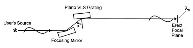
The SNR Monochromator is based on the novel1 and patented2 tuning geometry illustrated below. A reflection grating is rotated about an axis normal to its surface. An incident ray now views a groove spacing which has, in effect, increased as projected onto the dispersion plane. Therefore, the wavelength dispersed onto the stationary exit slit is scaled in proportion:

snr-sxr-fig1

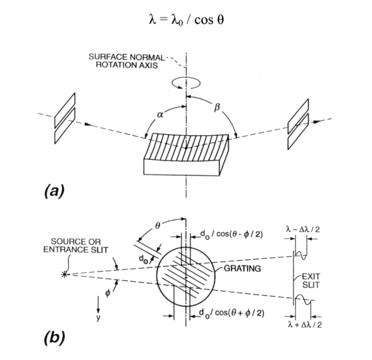
Fig. 1. Geometry of a simple surface normal rotation (SNR) fixed-slit grating monochromator. (a) Three-dimensional perspective where the grating is oriented to diffract the minimum wavelength through the exit slit. (b) Top view of the rotated grooves showing the groove spacings projected upon the sagittal incident rays, resulting in a limit to the spectral resolution. The same rotation technique may be used to construct other optical systems including plane grating designs, those employing auxiliary mirrors, and those where the slit(s) may move.

Because the optical surface is unchanged in position and orientation by such motion, the grating maintains its focusing properties, such as its focal length and numerical aperture at the new wavelength. In the self-focusing geometry where the grating surface is concave, stationary entrance and exit slits can be maintained on the Rowland circle or other desirable focusing condition.

The mechanical advantage provided by the cosine dependence of tuned wavelength upon rotation angle is of great advantage at grazing incidence. In the conventional rotation of a grating within the dispersion plane, the required angular accuracy is a small fraction of the graze angle (for example, 1 part in 1000 of a graze angle of 2 degrees). However, in the present surface normal rotation scheme, the required accuracy is a small fraction of 90 degrees, independent of the graze angle, representing a relaxation of 1 to 2 orders of magnitude.

Furthermore, due largely to the increase in effective groove spacing in proportion to the wavelength, the grating is maintained closer to the blazed condition of specular reflection from the groove facet as wavelength is tuned. This provides a significantly wider tuning range than possible with conventional rotation which tilts the groove facets away from the blazed direction.

The limitation of this simple geometry is the tilt of the image at the exit slit, which increases in linear proportion to the illuminated aperture Φ in the non-dispersive (sagittal direction). For non-rotating slits, this limits the spectral resolution to:

Δλ / λ = Φ tanθ

For example, with Φ = 2 mrad and θ = 78.5 degrees, a fractional wavelength resolution of less than 1/100 is maintained over a factor five scan in wavelength.

The SNR geometry is particularly advantageous when a large fixed target must be illuminated by a constant beam size over a broad range in wavelength.

snr-sxr-fig2

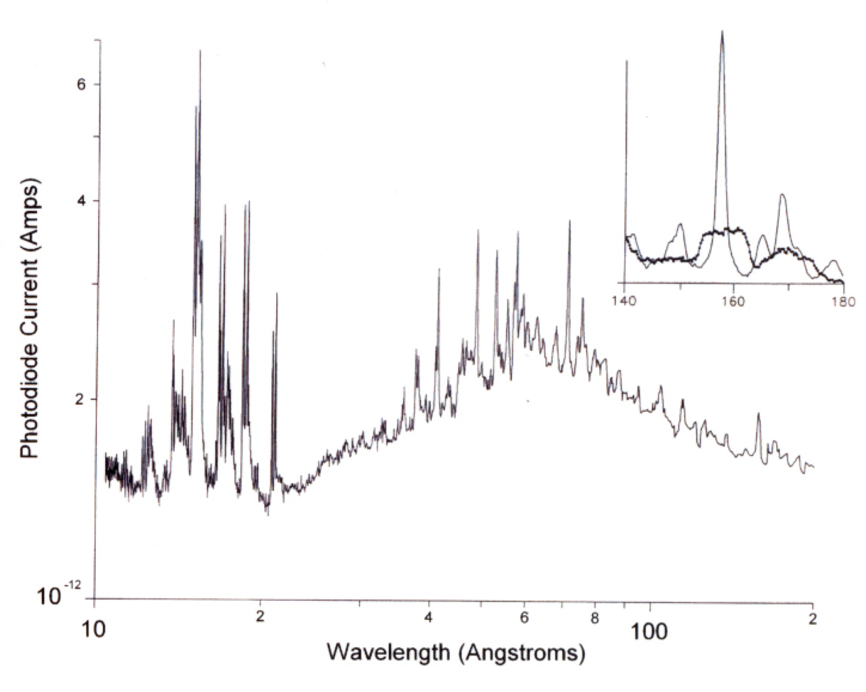
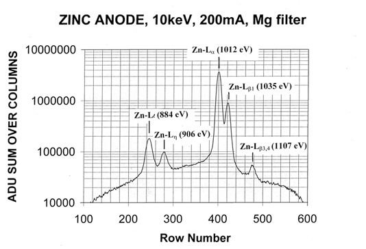
Fig. 2. Spectrum of a type 303 stainless-steel laser-plasma source obtained by using a sagittal aperture of 1 mrad and an exit-slit width of 20 µm. The heavy curve in the inset shows the degradation in spectral resolution caused by an increased (4-mrad) sagittal aperture. The light curve in the inset shows a factor of 6 improvement obtained by tilting the exit slit for optimum performance at a wavelength of 15.8 nm.

1 M.C. Hettrick, “Surface normal rotation: a new technique for grazing incidence monochromators,” Appl. Opt. 31, 7174 (1992)

2 U.S. Patent No. 5,274,435.

CAL-32 left details

Download product pdf

These anode cap sets are designed to be used with the Manson electron impact sources1, models 2 and 5. As enumerated in the table, the anode library provides a multitude of characteristic lines from K, L and M-shell transitions, as well as Bremsstrahlung continua. The ability to select spectral lines at closely spaced soft x-ray photon energies allows the calibration of spectral features such as filter absorption edges, multilayer (Bragg) interference reflectance peaks and grating efficiency variations (see Fig. 2) without resorting to the use of a synchrotron radiation facility.

The same anode set fits both model 2 and model 5 Manson sources. As specified for each material in the table, the anode caps are constructed of either a) the metal itself, or b) a base of 303 stainless steel with the impact material affixed to the top using low-outgassing silver conductive epoxy. Each anode cap is vented and, following initial break-in, is compatible with vacuum into the 10-8 mbar range. With the exception of Be, all anode caps are reusable indefinitely by nylon pad cleaning of the anode surface after extended use.

Fig. 1 shows the spectrum produced by one typical anode material (zinc), consisting of several useable characteristic L-shell lines, plus an underlying continuum for the atomic number Z=30. As the Bremsstrahlung strength is highly dependent upon Z, the strongest continuum is obtained using tantalum (Z=73) or tungsten (Z=74). Anode set model CAL-32 comprises the following materials: Be(4), B, C, Sapphire, Mg, Al, Si, Sc, Ti, V, Cr, Mn, Fe, SS303, Co, Ni, Cu, Zn, Ge, Y, Zr, Nb, Mo, Ru,Pd, Ag, Sn, Ta and W); refer to the characteristic emission line table for the available photon energies.

As an option, enhanced cooling of the operating anodes is available, using forced-air fans combined with a copper-block finned radiator. This is found to improve the positional stability of the emission region of the Manson source and stabilize its output intensity through reduced hydrocarbon contamination.

cal-32-fig1

Fig. 1. Spectrum of characteristic lines and Bremsstrahlung continuum from a zinc anode in the Manson model 2 source, using Hettrick SXR-II spectrometer and a CCD detector to record the spectrum.

cal-32-fig2
Fig. 2. Absolute efficiency measurements of a free-standing transmission grating, using numerous characteristic lines from CAL-32 anode library and Hettrick SXR-II monochromator.

1 Manson electron impact sources are manufactured and sold by Austin Instruments, Inc.
website: www.austinst.com
email: austinst@tiac.net
tel: 800-818-7403.

CAL-32 details main

CAL-32
Custom Anode Library

Characteristic Emission Lines from Electron-Impact Source

Photon
Energy
Species Material
49.3 eV Mg-L/M Mg (a)
72.4 eV Al-L/M Al (a)
Sapphire (b)
91.5 eV Si-L/M Si (b)
108.5 eV Be-K Be (b)
132.8 eV Y-Mz Y (b)
151.1 eV Zr-Mz Zr (a,b)
171.7 eV Nb-Mz Nb (a,b)
183.3 eV B-K B (b)
192.6 eV Mo-Mz Mo (a,b)
237 eV Ru-Mz Ru (b)
Energy Species Material
260 eV Rh-Mz Rh (b)
277 eV C-K Graphite (a)
284.4 eV Pd-Mz Pd (b)
311.7 eV Ag-Mz Ag (a)
348.3 eV Sc-Ll Sc (b)
352.9 eV Sc-Le Sc (b)
395.3 eV Ti-Ll Ti (a,b)
395.4 eV Sc-La Sc (b)
397 eV Sn-Mz Sn (a)
399.6 eV Sc-Lb Sc (b)
401.3 eV Ti-Le Ti (a,b)
Energy Species Material
446.5 eV V-Ll V (a)
452.2 eV Ti-La Ti (a,b)
458.4 eV Ti-Lb Ti (a,b)
500.3 eV Cr-Ll Cr (b)
510.2 eV Cr-Le Cr (b)
511.3 eV V-La V (a)
519.2 eV V-Lb V (a)
524.9 eV O-K Sapphire (b)
556.3 eV Mn-Ll Mn (b)
567.5 eV Mn-Le Mn (b)
572.8 eV Cr-La Cr (b)
582.8 eV Cr-Lb Cr (b)
615.2 eV Fe-Ll Fe/SS303 (a)
628 eV Fe-Le Fe/SS303 (a)
Energy Species Material
637.4 eV Mn-La Mn (b)
648.8 eV Mn-Lb Mn (b)
677.8 eV Co-Ll Co (b)
694 eV Co-Le Co (b)
705 eV Fe-La Fe/SS303 (a)
718.5 eV Fe-Lb Fe/SS303 (a)
742.7 eV Ni-Ll Ni (a)
762 eV Ni-Le Ni (a)
776.2 eV Co-La Co (b)
791.4 eV Co-Lb Co (b)
Photon
Energy
Species Material
811.1 eV Cu-Ll Cu (a)
832 eV Cu-Le Cu (a)
851.5 eV Ni-La Ni (a)
868.8 eV Ni-Lb Ni (a)
884 eV Zn-Ll Zn (a)
929.7 eV Cu-La Cu (a)
949.8 eV Cu-Lb Cu (a)
1011.7 eV Zn-La Zn (a)
1034.7 eV Zn-Lb Zn (a)
1036.2 eV Ge-Ll Ge (b)
Energy Species Material
1068 eV Ge-Le Ge (b)
1188 eV Ge-La Ge (b)
1218.5 eV Ge-Lb Ge (b)
1253.6 eV Mg-Ka Mg (a)
1302.2 eV Mg-Kb Mg (a)
1380 eV W-Mz W (b)
1486.7 eV Al-Ka Al (a)
Sapphire (b)
1557.5 eV Al-Kb Al (a)
Sapphire (b)
1685.4 eV Y-Ll Y (b)
1710 eV Ta-Ma Ta (a)
1740 eV Si-Ka Si (b)
Energy Species Material
1774 eV W-Ma W (b)
1761 eV Y-Le Y (b)
1792 eV Zr-Ll Zr (a,b)
1835.9 eV Si-Kb Si (b)
1876.5 eV Zr-Le Zr (a,b)
1902.2 eV Nb-Ll Nb (a,b)
1922.6 eV Y-La Y (b)
1996.2 eV Nb-Le Nb (a,b)
2015.7 eV Mo-Ll Mo (a,b)
2042.4 eV Zr-La Zr (a,b)
Energy Species Material
2165.9 eV Nb-La Nb (a,b)
2253 eV Ru-Ll Ru (b)
2293.2 eV Mo-La Mo (a,b)
2559 eV Ru-La Ru (b)
2697 eV Rh-La Rh (b)
2839 eV Pd-La Pd (b)
2984 eV Ag-La Ag (a)
3444 eV Sn-La Sn (a)
4091 eV Sc-Ka Sc (b)
4511 eV Ti-Ka Ti (a,b)
4952 eV V-Ka V (a)
5415 eV Cr-Ka Cr (b)
– – –

ES-XUV left details

Download product pdf


• Erect Field: Small Flat Detection Surface
• Grazing Incidence: XUV
• VLS: Ultra-High Spectral Resolution
• Fixed Optics: Robust Stability
• Astigmatic: High Throughput, Compact
• Monochromator Conversion (optional)


ES-XUV Specifications

Mounting
Hettrick, VLS plane grating

Angle-of-Incidence (α)
87.75°(gratings SX/SA/SB)
85.25°(focusing mirror)

Master Grating Format
Gold surface, 62 x 15 mm

Mirror Format
Gold surface, 50 mm

Vacuum Chamber
9″ X 6″ X 5.5″, plus legs
[Weld-free electroless nickel plated 6061 aluminum]

Vacuum Compatibility
10-8 torr

User ports
TEFLAT/BLACKFLAT™ gasket-sealed knife-edge flanges – ICF070 (3), ICF114 (1)

Weight
12kg

Source – focal plane
5.6 meters

Meridional Aperture
1 mrad

Sagittal Aperture
10 mrad

ES-XUV details main

Opto-Mechanical Design

A grazing incidence varied line-space (VLS) diffraction grating provides a normal incidence spectrum, allowing efficient use of CCD and other electronic detectors. The Edge Spectrograph is an astigmatic, fixed-optic design, with ultra-high resolution model ES-XUV derived from initial applications of measuring gain narrowing in XUV lasers at a resolving power of up to ~ 20,000. There are no feedthrough adjustments of the optics, resulting in a simple, low-cost design. Each grating is mounted to a dedicated vacuum flange which is exchanged at atmosphere to select the desired spectral region. Fine-tuning of the spectral focus is achieved by the user adjusting his point source position.

Alternatively, an optional entrance slit assembly provides a micrometer feedthrough positioning adjustment of the slits, for use with a spatially extended source. Four manually-adjustable honed knife-edges at the entrance port of the optics chamber define the illuminated aperture, and one knife-edge is placed at the position of minimum confusion above the focusing mirror to reduce stray light. The aluminum optics chamber is supplied with mounting legs which can be bolted directly to an inch-spacing threaded hole (1/4-20) user-supplied breadboard. The user also provides the light source and detector along with their connecting nipples to the optics chamber, and vacuum pumps/gages.

The spectrograph includes 3 master gratings (SX/SA/SB), each mounted on a dedicated ICF114 knife-edge flange with engraved nameplate and gasket-sealed storage cylinder. The groove profiles for all three gratings were traced using STM (Scanning Tunneling Microscopy). The resulting micrographs (Fig. 2) reveal nearly perfectly flat groove facets, leading to near-theoretical diffraction efficiencies peaking at the blazed wavelength.

Conversion to a monochromator may be conveniently implemented by the user providing a simple linear translation of the light source along the erect flat-field spectral plane. In this case, the direction of propagation is reversed such that a stationary exit slit is positioned in place of the light source shown on the left side of the given optical schematic (Fig. 1). Details of such a conversion depend upon the optical and mechanical characteristics of the user’s light source, and should be discussed with Hettrick Scientific to evaluate its feasibility and ease-of-use for the intended application.

Grating Band Specifications
g/mm Center
mλc (1)
Range
mλc (2)
order Plate Scales (4)
@source @focal plane (3)
SX 1500 48 Å 35-70 Å inside 0.19 Å/mm 0.20 Å/mm
SA 750 96 Å 70-140 Å inside 0.38 Å/mm 0.40 Å/mm
SB 375 192 Å 140-280 Å inside 0.76 Å/mm 0.80 Å/mm

(1) Center wavelength is the wavelength (x spectral order, m) dispersed along the principal ray (parallel to the incident sea-level ray to the mirror-grating system. This angular direction is also that which is blazed (local specular reflection from 2.5° apex angle triangular grooves).

(2) Given the two-reflection optical system of model ES-XUV (Fig. 1) and the excellent groove profiles (Fig. 2), the absolute efficiency is still usable in second order (m=2) at a wavelength of O-K (23.6 Angstroms), which will appear and also be blazed near the central blazed first order (m=1) wavelength of 48 Angstroms (2 x 23.6 = 47.2 Angstroms). The high efficiency range of first order wavelengths given in the above table are those dispersed over an erect field width of 165 mm, requiring re-positioning of commercially available CCDs (~ 27 mm width format), or use of film.

(3) Plate scales at focal plane are a function of the diffraction angle and hence the dispersed wavelength; nominal values given.

(4) Due to the small optical aberrations from the varied-line space gratings, one calculates from the above plate scales a net FWHM spectral resolving power at the central wavelength (any grating or spectral order) of approximately 48/(MAX + 0.5*MIN), where MAX = maximum of [0.19 A/mm x (entrance slit width), 0.20 A/mm x (detector pixel width)]. Assuming an entrance slit of 10 microns and a CCD pixel width of 12.5 microns yields a resolving power ~ 14,000. Because the resolving power increases longward of the central wavelength, the initial customer’s XUV laser application measured a resolving power of ~ 16,000 at 234 Angstroms using grating SB.

Fig. 1. Schematic of ES-XUV optical system. The flat-field spectrum is dispersed about the center wavelength (λc) onto a normal incidence detector. In this standard mounting, dispersion is vertical and the optical axes incident and exiting the optics chamber are at sea-level.

es-xuv-fig1

Fig. 2. Scanning tunneling micrographs (STMs) of master grating grooves for model ES-XUV spectrometer: a) nominal 375 g/mm grating; b) nominal 750 g/mm grating and c) nominal 1500 g/mm grating.es-xuv-fig1

VSA-200 detail_left

Download product pdf

Slits are required for use under vacuum in spectrometers, imaging systems and interferometers operating at far UV, extreme UV and soft X-ray photon energies.

Model VSA-200 vacuum slit assemblies are used in all Hettrick Scientific spectrometers, and are now available for separate purchase.

VSA-200 detail main

VSA-200 Product Details


This assembly is mounted inside a 4.5 inch (ICF114) double-sided (1.50 inch thickness) electroless nickel coated aluminum chamber, with knife-edge flange faces which may be sealed using TEFLAT™ or BLACKFLAT™ gaskets or rectangular cross-section o-rings. A slit mask consisting of 6 slits travels on a preloaded crossed roller slide under vacuum, driven by an o-ring sealed linear feedthrough shaft of a precision micrometer with 1 micron digital readout. This mechanism provides for both selection of the slit and fine adjustment of its position in the beam.

To avoid illumination of other than the selected slit, a removable light baffle plate having a central opening covers the entrance port. A high resolution slit mask provides nominal widths of 5, 10, 20, 50, 100 and 200 microns and length of 20 mm. The actual calibrated slit widths are given for each mask to within 10%. An optional low resolution slit mask provides widths of 75, 100, 150, 200, 300 and 400 microns and length of 15 mm. The chamber is machined true and square with external sides precisely oriented (parallel and perpendicular) relative to the internal slits, enabling a convenient and accurate mechanical reference.

The tapped hole mounting pattern on both sides of the chamber, using stainless steel helicoil inserts for maximum strength and cleanliness, mates to commercially available English size knife edge flanges. To allow the slit chamber to be bolted directly to a tapped hole chamber, counterbored clearance holes on a 3.75 inch square pattern are also available at the corners of the chamber, as shown in the photograph. Threaded holes (1/4-20) in the slit chamber side also provide for mounting on a table bracket (optional). All materials residing inside vacuum are vented and cleaned for compatibility with high vacuum (low 10-8 torr).

Older Posts

HomeLeft

VSA-200 listing

VSA-200

VSA-200_thumb
In-vacuum selection of optical slits.

Product Details

CAL-32 ANODE LIBRARY listing

CAL-32

Anode_thumbAnodes for electron-beam Manson ultrasoft x-ray light sources.

Product Details

TEFLAT/BLACKFLAT listing

TEFLAT/BLACKFLAT

gaskets_thumbClean & reusable vacuum gaskets

Product Details

Application/Feasibility Analysis listing

Application/Feasibility Analysis

Technical study / written report of custom applications.

More Information

HardwareLeft

VSA-200

VSA-200_thumb
In-vacuum selection of optical slits.

Product Details

CAL-32

Anode_thumbAnodes for electron-beam Manson ultrasoft x-ray light sources.

Product Details

TEFLAT/BLACKFLAT

gaskets_thumbClean & reusable vacuum gaskets

Product Details

ServicesLeft

Application/Feasibility Analysis

Technical study / written report of custom applications.

More Information

Staff

Michael Charles Hettrick


hettrick_thumbCurriculum Vitae

More Information

ES-SXL

Download product pdf


• Erect Field: Small Flat Detection Surface
• Grazing Incidence: Soft X-Ray / EUV / FUV
• VLS: High Spectral Resolution
• Fixed Optics: Robust Stability
• Astigmatic: High Throughput, Compact
• Monochromator Conversion (optional)


ES-SXR Specifications

Mounting
Hettrick, VLS plane grating

Angle-of-Incidence (α)
87.25° (gratings A/B/C/D)
88.75° (SA/SB/SC/SD)
88.00° (focusing mirror)

Replica Grating Format
Gold surface, 62 x 15 mm

Mirror Format
Gold surface, 50 or 100 mm

Vacuum Chamber
9″ X 6″ X 5.5″, plus legs
[Weld-free electroless nickel plated 6061 aluminum]

Vacuum Compatibility
10-8 torr

User ports
TEFLAT/BLACKFLAT gasket-sealed knife-edge flanges – ICF63 (3), ICF114 (1)

Weight
12kg

Source – focal plane
1.75 meters

Meridional Aperture
3.8 mrad (gratings A/B/C/D)
1.75 mrad (SA/SB/SC/SD)

Sagittal Aperture
15 mrad (astigmatic)

curriculum left

Personal


Birthdate: July 29, 1958.
Birthplace: New Britain, Connecticut, U.S.A.

Doctoral Thesis

Selected Journal Publications (28)

More Information

U.S. Letters Patents (4)

More Information

VSA-200 Left

Download product pdf

Slits are required for use under vacuum in spectrometers, imaging systems and interferometers operating at far UV, extreme UV and soft X-ray photon energies.

Model VSA-200 vacuum slit assemblies are used in all Hettrick Scientific spectrometers, and are now available for separate purchase.

ES-XUV details left

Download product pdf


• Erect Field: Small Flat Detection Surface
• Grazing Incidence: XUV
• VLS: Ultra-High Spectral Resolution
• Fixed Optics: Robust Stability
• Astigmatic: High Throughput, Compact
• Monochromator Conversion (optional)


ES-XUV Specifications

Mounting
Hettrick, VLS plane grating

Angle-of-Incidence (α)
87.75°(gratings SX/SA/SB)
85.25°(focusing mirror)

Master Grating Format
Gold surface, 62 x 15 mm

Mirror Format
Gold surface, 50 mm

Vacuum Chamber
9″ X 6″ X 5.5″, plus legs
[Weld-free electroless nickel plated 6061 aluminum]

Vacuum Compatibility
10-8 torr

User ports
TEFLAT/BLACKFLAT™ gasket-sealed knife-edge flanges – ICF070 (3), ICF114 (1)

Weight
12kg

Source – focal plane
5.6 meters

Meridional Aperture
1 mrad

Sagittal Aperture
10 mrad

SNR-SXR

Download product pdf

U.S. Patent 5,274,435

  • Self-Focusing Concave Grating
    – High Throughput
  • Grazing Incidence: Soft X-Ray Use
  • Stationary Slits
  • Fixed Beam Directions
  • Fixed Numerical Aperture
  • Broadband Tunability

Specifications

Mounting
Hettrick, U.S. Patent 5,274,435; Spherical Grating
Angular Deviation
4.5°(Fixed). Nominal graze angle of 2.25°
Grating Stage Format
Gold Surface;
Active Circular Aperture 100 mm
Grating Groove Density
750 g/mm
Wavelength Range
10~100 Angstroms (m=1); approx. 6~50 Angstroms (m=2), depending on source intensity
Fractional Dispersive Resolution
0.167/mm (at Source and Exit Slit)
Optical Aberration (image tilt)
Δλ/λ < 0.010 at 6 mrad Sagittal Aperture, 10~50 Angstroms (m=1)
Meridonial Aperture
12.5 mrad, on Rowland Circle
Sagittal Aperture
0~30 mrad, astigmatic (Φ)
Exit Slit Width (Vacuum Selectable)
200 µm at 0.2°
100 µm at 0.2° (10-13 Å)
100 µm at 0.7° (13-20 Å)
100 µm at 1.2° (20-28 Å)
100 µm at 1.7° (28-37 Å)
100 µm at 2.2° (> 37 Å)
Exit Slit Length
20 mm
External Drive
Single Micro-Stepped Motor with Compumotor ZETA6104-57-83 Indexer/Drive w/RS232C Interface Port
Vacuum Chamber
Weld-Free 6061 Aluminum, Electroless Nickel Plated; TEFLAT/BLACKFLAT Sealed Knife-edge Ports
Entrance and Exit Ports
4.5″ Conflat Flange (ICF114)
User Ports
Three Ports Accept 2.75″ Conflat Flange (ICF070)
Length
0.63 meters (Slit-Slit)
Aperture Center
Stationary

Construction

Model SNR-SXR-0.6 is a high aperture (Φ = 12.5 mrad), single-element soft x-ray Monochromator. The grating has a 100 mm circular aperture with grooves extending to the edge. The distance from (slitless) source to exit slit is 628 mm. The fixed angular deviation of 4.5 degrees and gold coated grating provide efficient reflection to wavelengths as short as λmin = 10 Angstroms in first order and to approximately 6 Angstroms in second order. The spectral resolution is determined by the sagittal aperture which may be set by knife-edges at the entrance port of exit slit, over the range of approximately 0 to 30 mrad. A typical setting of 3 mrad (illuminating 2 mm at the exit slit) provides a fractional spectral resolution of 1/160 at 23 Å, 1/68 at 50 Å, and 1/33 at 100 Å. However, the long wavelength performance is improved considerably by employing an exit slit mask containing 6 slits (100 µm wide) at different angles, to match the image tilt over different regions in scanned wavelength. Using the appropriate slit, the resolution is approximately 1/100 over 10~50 Å using a 6 mrad sagittal aperture.

An externally mounted micro-stepping motor with Compumotor indexer provides rotational control of the grating scan under vacuum by means of a shaft feedthrough. The slits are also selectable under vacuum using a micrometer shaft feedthrough. Both the grating chamber and the slit chambers are electroless-nickel plated aluminum and are machined square relative to the grating surface and slit mask, enabling alignment by mechanical indication from the chamber exteriors.

The photograph shows a custom system including model SNR-SXR-0.6 and associated optional equipment (not included with base instrument) such as a Manson model 2 soft x-ray source and compact chamber, pumps, gages, mounting table and brackets, CCD, filter assembly, vacuum-selectable aperture and microscope visible alignment system, for calibrating x-ray transmission gratings in the 5-114 Å region.

snr-sxr-fig3

CAL-32

Download product pdf

These anode cap sets are designed to be used with the Manson electron impact sources1, models 2 and 5. As enumerated in the table, the anode library provides a multitude of characteristic lines from K, L and M-shell transitions, as well as Bremsstrahlung continua. The ability to select spectral lines at closely spaced soft x-ray photon energies allows the calibration of spectral features such as filter absorption edges, multilayer (Bragg) interference reflectance peaks and grating efficiency variations (see Fig. 2) without resorting to the use of a synchrotron radiation facility.

The same anode set fits both model 2 and model 5 Manson sources. As specified for each material in the table, the anode caps are constructed of either a) the metal itself, or b) a base of 303 stainless steel with the impact material affixed to the top using low-outgassing silver conductive epoxy. Each anode cap is vented and, following initial break-in, is compatible with vacuum into the 10-8 mbar range. With the exception of Be, all anode caps are reusable indefinitely by nylon pad cleaning of the anode surface after extended use.

Fig. 1 shows the spectrum produced by one typical anode material (zinc), consisting of several useable characteristic L-shell lines, plus an underlying continuum for the atomic number Z=30. As the Bremsstrahlung strength is highly dependent upon Z, the strongest continuum is obtained using tantalum (Z=73) or tungsten (Z=74). Anode set model CAL-32 comprises the following materials: Be(4), B, C, Sapphire, Mg, Al, Si, Sc, Ti, V, Cr, Mn, Fe, SS303, Co, Ni, Cu, Zn, Ge, Y, Zr, Nb, Mo, Ru,Pd, Ag, Sn, Ta and W); refer to the characteristic emission line table for the available photon energies.

As an option, enhanced cooling of the operating anodes is available, using forced-air fans combined with a copper-block finned radiator. This is found to improve the positional stability of the emission region of the Manson source and stabilize its output intensity through reduced hydrocarbon contamination.

cal-32-fig1

Fig. 1. Spectrum of characteristic lines and Bremsstrahlung continuum from a zinc anode in the Manson model 2 source, using Hettrick SXR-II spectrometer and a CCD detector to record the spectrum.

cal-32-fig2
Fig. 2. Absolute efficiency measurements of a free-standing transmission grating, using numerous characteristic lines from CAL-32 anode library and Hettrick SXR-II monochromator.

1 Manson electron impact sources are manufactured and sold by Austin Instruments, Inc.
website: www.austinst.com
email: austinst@tiac.net
tel: 800-818-7403.

Ultimate Posts

Download product pdf

TEFLAT™/BLACKFLAT™ gaskets provide many advantages when compared to conventional sealing materials for knife-edge flanges:

• Require much less force than copper, significantly reducing assembly time (and saving knuckles!).
• May be used with aluminum (or stainless steel) flanges and ports.
• Unlike copper gaskets, Teflon® gaskets are reusable, if not removed from flange and kept clean (number of re-uses may vary).
• Unlike copper gaskets, Teflon® gaskets do not tarnish with exposure to air.
• Unlike copper gaskets or o-rings, Teflon® does not react with most chemicals.
• Avoids the use of grease often necessary to keep thin section o-rings registered in place during assembly, particularly for a vertical flange orientation.
• Minimizes contamination of vacuum systems, particularly important for coating applications, high purity analyses and ultra-high vacuum applications.
• Unlike thin section o-rings, rigid Teflon® gaskets self-locate against the flange lip to provide a clear confirmation of a correct seal, preventing leaks and extruded o-rings.
• Less expensive than rectangular section o-rings.

Copyright © 2023 Hettrick Scientific. All rights reserved.