Opto-Mechanical Design
A grazing incidence varied line-space (VLS) diffraction grating provides a normal incidence spectrum, allowing efficient use of CCD and other electronic detectors. The Edge Spectrograph is an astigmatic, fixed-optic design, with ultra-high resolution model ES-XUV derived from initial applications of measuring gain narrowing in XUV lasers at a resolving power of up to ~ 20,000. There are no feedthrough adjustments of the optics, resulting in a simple, low-cost design. Each grating is mounted to a dedicated vacuum flange which is exchanged at atmosphere to select the desired spectral region. Fine-tuning of the spectral focus is achieved by the user adjusting his point source position.
Alternatively, an optional entrance slit assembly provides a micrometer feedthrough positioning adjustment of the slits, for use with a spatially extended source. Four manually-adjustable honed knife-edges at the entrance port of the optics chamber define the illuminated aperture, and one knife-edge is placed at the position of minimum confusion above the focusing mirror to reduce stray light. The aluminum optics chamber is supplied with mounting legs which can be bolted directly to an inch-spacing threaded hole (1/4-20) user-supplied breadboard. The user also provides the light source and detector along with their connecting nipples to the optics chamber, and vacuum pumps/gages.
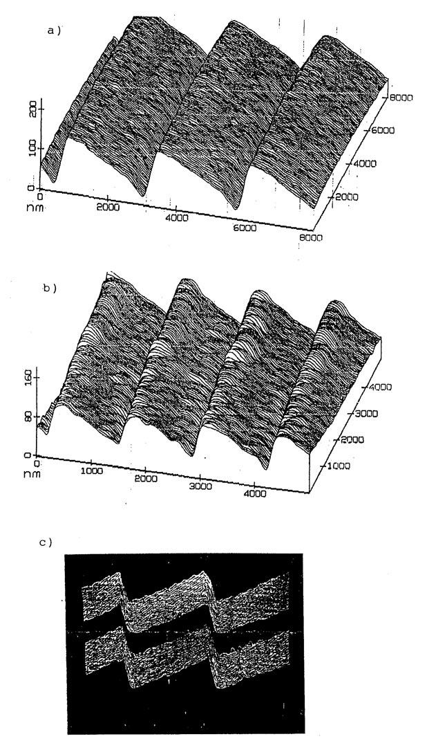
The spectrograph includes 3 master gratings (SX/SA/SB), each mounted on a dedicated ICF114 knife-edge flange with engraved nameplate and gasket-sealed storage cylinder. The groove profiles for all three gratings were traced using STM (Scanning Tunneling Microscopy). The resulting micrographs (Fig. 2) reveal nearly perfectly flat groove facets, leading to near-theoretical diffraction efficiencies peaking at the blazed wavelength.
Conversion to a monochromator may be conveniently implemented by the user providing a simple linear translation of the light source along the erect flat-field spectral plane. In this case, the direction of propagation is reversed such that a stationary exit slit is positioned in place of the light source shown on the left side of the given optical schematic (Fig. 1). Details of such a conversion depend upon the optical and mechanical characteristics of the user’s light source, and should be discussed with Hettrick Scientific to evaluate its feasibility and ease-of-use for the intended application.
| g/mm | Center mλc (1) |
Range mλc (2) |
order | Plate Scales (4) | ||
|---|---|---|---|---|---|---|
| @source | @focal plane (3) | |||||
| SX | 1500 | 48 Å | 35-70 Å | inside | 0.19 Å/mm | 0.20 Å/mm |
| SA | 750 | 96 Å | 70-140 Å | inside | 0.38 Å/mm | 0.40 Å/mm |
| SB | 375 | 192 Å | 140-280 Å | inside | 0.76 Å/mm | 0.80 Å/mm |
(1) Center wavelength is the wavelength (x spectral order, m) dispersed along the principal ray (parallel to the incident sea-level ray to the mirror-grating system. This angular direction is also that which is blazed (local specular reflection from 2.5° apex angle triangular grooves).
(2) Given the two-reflection optical system of model ES-XUV (Fig. 1) and the excellent groove profiles (Fig. 2), the absolute efficiency is still usable in second order (m=2) at a wavelength of O-K (23.6 Angstroms), which will appear and also be blazed near the central blazed first order (m=1) wavelength of 48 Angstroms (2 x 23.6 = 47.2 Angstroms). The high efficiency range of first order wavelengths given in the above table are those dispersed over an erect field width of 165 mm, requiring re-positioning of commercially available CCDs (~ 27 mm width format), or use of film.
(3) Plate scales at focal plane are a function of the diffraction angle and hence the dispersed wavelength; nominal values given.
(4) Due to the small optical aberrations from the varied-line space gratings, one calculates from the above plate scales a net FWHM spectral resolving power at the central wavelength (any grating or spectral order) of approximately 48/(MAX + 0.5*MIN), where MAX = maximum of [0.19 A/mm x (entrance slit width), 0.20 A/mm x (detector pixel width)]. Assuming an entrance slit of 10 microns and a CCD pixel width of 12.5 microns yields a resolving power ~ 14,000. Because the resolving power increases longward of the central wavelength, the initial customer’s XUV laser application measured a resolving power of ~ 16,000 at 234 Angstroms using grating SB.
Fig. 1. Schematic of ES-XUV optical system. The flat-field spectrum is dispersed about the center wavelength (λc) onto a normal incidence detector. In this standard mounting, dispersion is vertical and the optical axes incident and exiting the optics chamber are at sea-level.
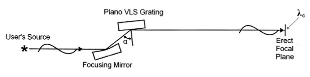
Fig. 2. Scanning tunneling micrographs (STMs) of master grating grooves for model ES-XUV spectrometer: a) nominal 375 g/mm grating; b) nominal 750 g/mm grating and c) nominal 1500 g/mm grating.