Opto-Mechanical Design
A grazing incidence varied line-space (VLS) diffraction grating provides a normal incidence spectrum, allowing efficient use of CCD and other electronic detectors. The Edge Spectrograph is an astigmatic, fixed-optic design, with model ES-SXR providing a resolving power up to ~ 2,000. Initially applied to analyzing the K-edges of Silicon and Oxygen for CCD characterization and those of Aluminum and Oxygen for thin-film filter calibration, the design has also proven ideal for characterization of LPP, HHG and Z-pinch light sources. There are no feedthrough adjustments of the optics, resulting in a simple, low-cost design. Each grating is mounted to a dedicated vacuum flange which is exchanged at atmosphere to select the desired spectral region. Fine-tuning of the spectral focus is achieved by the user adjusting his point source position.
Alternatively, an optional entrance slit assembly provides a micrometer feedthrough positioning adjustment of the slits, for use with a spatially extended source. Four manually-adjustable honed knife-edges at the entrance port of the optics chamber define the illuminated aperture, and one knife-edge is placed at the position of minimum confusion above the focusing mirror to reduce stray light. The aluminum optics chamber is supplied with mounting legs which can be bolted directly to an inch-spacing threaded hole (1/4-20) user-supplied breadboard. The user also provides the light source and detector along with their connecting nipples to the optics chamber, and vacuum pumps/gages.
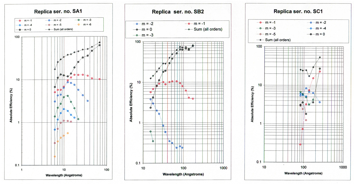
The spectrograph includes 4 replica gratings (SA/SB/SC/SD or A/B/C/D), each mounted on a dedicated ICF114 knife-edge flange with engraved nameplate and gasket-sealed storage cylinder. Absolute efficiency calibrations of sample gratings SA, SB and SC are given in Fig. 2.
Conversion to a monochromator may be conveniently implemented by the user providing a simple linear translation of the light source along the erect flat-field spectral plane. In this case, the direction of propagation is reversed such that a stationary exit slit is positioned in place of the light source shown on the left side of the optical schematic (Fig. 1). Details of such a conversion depend upon the optical and mechanical characteristics of the user’s light source, and should be discussed with Hettrick Scientific to evaluate its feasibility and ease-of-use for the intended application.
This spectrograph/monochromator workhorse provides access to over two decades in wavelength (6 ~ 2000 Angstroms) covering the soft x-ray, EUV and FUV spectral regions.
Grating Band Specifications
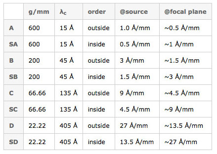
Fig. 1. Schematic of ES-SXR optical system. The flat-field spectrum is dispersed about the center wavelength (λc) onto a normal incidence detector. In this standard mounting, dispersion is vertical and the optical axes incident and exiting the optics chamber are at sea-level.
Efficiency Calibration
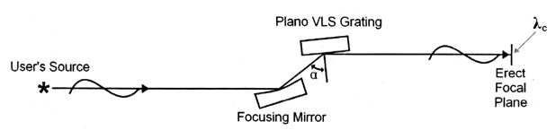
Fig. 2. Efficiency calibration of individual replica gratings. Angle-of-incidence is 88.75°. Illuminated region within active ru1ed aperture of 15 mm x 62.5 mm is approximately 5 mm along groove lengths by 5-20 mm in ruled width direction, depending upon the wavelength. These results are certified only for these specific serial number gratings and do not constitute a representation or approximation of efficiencies which may be obtained with other individual replicas or at other angles of incidence.