Background
Prior grazing incidence monochromators have performed scanning, or tuning of the wavelength transmitted through the exit slit, by use of motions solely within the dispersion plane normal to the grating grooves. Such scanning has comprised rotation of the grating about an axis parallel to its grooves, sometimes accompanied by translation of the grating or rotation and translation of mirrors and slits within this same dispersion plane. This historical constraint has resulted in several performance limitations, particularly when operated at grazing angles of incidence, including 1) a large fractional variation in the aperture as a function of tuned wavelength, 2) a narrow tuning range for efficient diffraction by a blazed grating, 3) a high required precision of grating and mirror rotation and slit translation, and typically 4) defocusing due to the dependence of the grating focal length upon incidence angle.
However, by discarding the geometrical convention of motions exclusively within the grating dispersion plane, and extending scanning to the third dimension, these performance limitations are overcome at grazing incidence.
Optical Principle
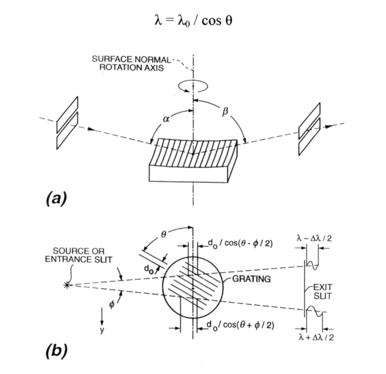
The SNR Monochromator is based on the novel1 and patented2 tuning geometry illustrated below. A reflection grating is rotated about an axis normal to its surface. An incident ray now views a groove spacing which has, in effect, increased as projected onto the dispersion plane. Therefore, the wavelength dispersed onto the stationary exit slit is scaled in proportion:

Fig. 1. Geometry of a simple surface normal rotation (SNR) fixed-slit grating monochromator. (a) Three-dimensional perspective where the grating is oriented to diffract the minimum wavelength through the exit slit. (b) Top view of the rotated grooves showing the groove spacings projected upon the sagittal incident rays, resulting in a limit to the spectral resolution. The same rotation technique may be used to construct other optical systems including plane grating designs, those employing auxiliary mirrors, and those where the slit(s) may move.
Because the optical surface is unchanged in position and orientation by such motion, the grating maintains its focusing properties, such as its focal length and numerical aperture at the new wavelength. In the self-focusing geometry where the grating surface is concave, stationary entrance and exit slits can be maintained on the Rowland circle or other desirable focusing condition.
The mechanical advantage provided by the cosine dependence of tuned wavelength upon rotation angle is of great advantage at grazing incidence. In the conventional rotation of a grating within the dispersion plane, the required angular accuracy is a small fraction of the graze angle (for example, 1 part in 1000 of a graze angle of 2 degrees). However, in the present surface normal rotation scheme, the required accuracy is a small fraction of 90 degrees, independent of the graze angle, representing a relaxation of 1 to 2 orders of magnitude.
Furthermore, due largely to the increase in effective groove spacing in proportion to the wavelength, the grating is maintained closer to the blazed condition of specular reflection from the groove facet as wavelength is tuned. This provides a significantly wider tuning range than possible with conventional rotation which tilts the groove facets away from the blazed direction.
The limitation of this simple geometry is the tilt of the image at the exit slit, which increases in linear proportion to the illuminated aperture Φ in the non-dispersive (sagittal direction). For non-rotating slits, this limits the spectral resolution to:
Δλ / λ = Φ tanθ
For example, with Φ = 2 mrad and θ = 78.5 degrees, a fractional wavelength resolution of less than 1/100 is maintained over a factor five scan in wavelength.
The SNR geometry is particularly advantageous when a large fixed target must be illuminated by a constant beam size over a broad range in wavelength.

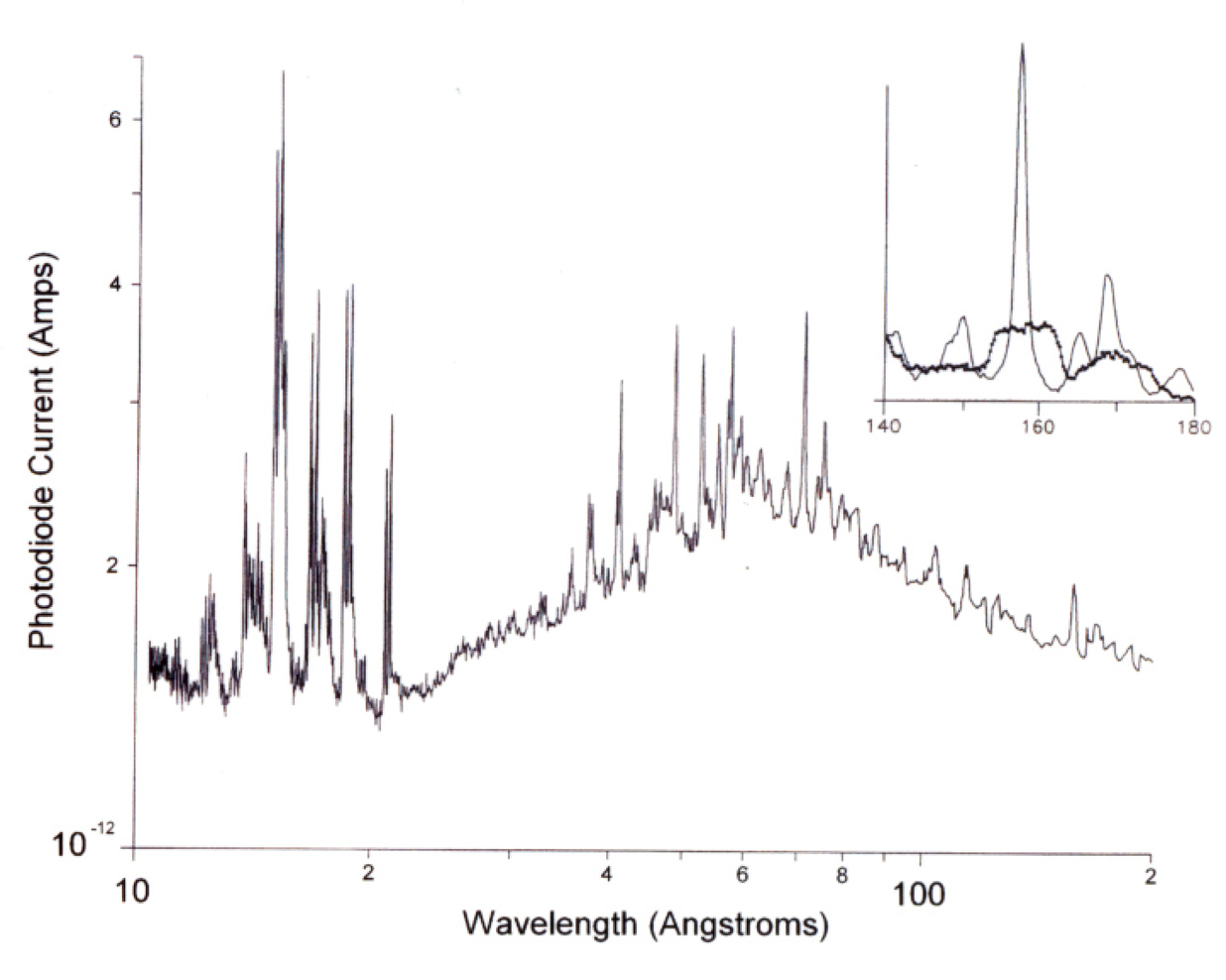
Fig. 2. Spectrum of a type 303 stainless-steel laser-plasma source obtained by using a sagittal aperture of 1 mrad and an exit-slit width of 20 µm. The heavy curve in the inset shows the degradation in spectral resolution caused by an increased (4-mrad) sagittal aperture. The light curve in the inset shows a factor of 6 improvement obtained by tilting the exit slit for optimum performance at a wavelength of 15.8 nm.
1 M.C. Hettrick, “Surface normal rotation: a new technique for grazing incidence monochromators,” Appl. Opt. 31, 7174 (1992)
2 U.S. Patent No. 5,274,435.